Wednesday 30 April 2014

Technical implementation in final installations

Text based installation

For the text based installation to be triggered unobtrusively it was necessary to use discrete technology, I considered various motion sensors compatible with the arduino. First of which was to have a pressure sensor embedded in the floor that when stepped on would trigger the installation. However it may be problematic with regards being a big enough size, it's possible that a visor would walk over it or passed it without standing on it. Another probability would be hiding it, it would need to register the footsteps but be at the same level of the floor. Another suggestion was to use a proximity sensor, however previous testing of this suggested it may be a bit temperamental especially if there are a lot of people in the museum space at once. 
Then it was considered to create an infrared beam to shine across to meet an infrared sensor. Of course infrared beams are undetectable by the human eye so it seemed a good choice. The idea is that once the beam is broken (ie. someone passes through it) the interaction would then be triggered.  Initial testing of this was conducted by writing a script that registered the infrared beam and once the beam was broken a yellow led would turn on. Pictured below is testing it with the infrared light of a tv remote. Later an infrared LED hooked up to the arduino was used. It was discovered that the beam would not be strong enough for the purpose of the project.


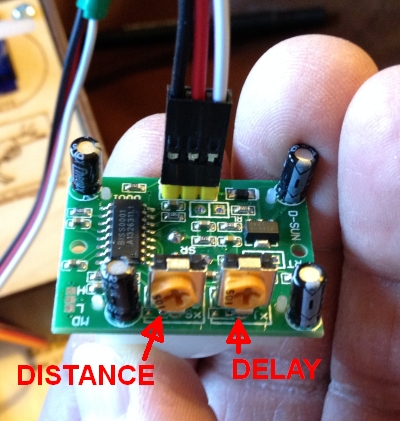
After further research online I came across a passive infrared sensor. The benefit of which is that another component wouldn't be required across the room. It wouldn't create a beam but detect an individuals motion by reading the infrared waves that radiate from them. The component itself has two variables, the sensitivity/distance and the time/delay. It took a lot of tweaking to get the desired result from this. For the purpose of the project it was calculated to the scale of the architectural model.


The program for this is written with Arduino software. It defines that pin7 is the input for the ir sensor and when triggered emits light from the leds behind the letters that create the desired words of the text. 
For the purpose of the scaled model the led's and sensor are all wired to the same arduino however the use of an xbee shield for the arduino would enable the two to be separate. Aswell as a delay in the time it takes for the leds to be triggered there is also a delay in the amount of times the sensor can be read. Exmaple: the infrared sensor will not trigger the led 
It is envisaged that when triggered, the letters are revealed in a gradual mode revealing the word letter by letter for the viewer(not the person who triggered the motion sensor) to see.


The video installation

For the video installation to be triggered a dial on the lantern must be turned. A rotary potentiometer was used. The potentiometer is wired to the Arduino. In the arduino platfrom the standard firmata was uploaded to the board. In processing it is programmed to change the display of the loaded videos. The projector used in the installation is a Dell 2400 MP. It is smaller than the average projector and fitted well into the housing. Had the budget being bigger for the project we would have invested in a short throw projector. To combat this problem of not having a short throw projector, we reflected the projection from a mirror back onto the book. For this reason the video content had to be reversed. After testing the projection in the housing we discovered that the brightness of the original video wasn't carried through to the projection. The image was a lot darker projected and it lost some detail. To fix this the original videos were brightened and the settings of brightness were also changed on the projector itself.

The lantern

The durability of the lantern is primary to the success of the installation. it will be interacted with the most and has a higher cance of being damaged. In the first prototype it was held in place with a cardboard structure in the base of the lantern. 
It was quickly discovered that this wouldn't be sufficently strong enough. The final piece will need a more durable housing. In this previous prototype there was no dial on the potentiometer and it may have been mistaken for a button. We have now sourced dials for the potentiometers which may help this too. We spray painted the lanterns black to give them a nice even finish which proved very succesfull. I cut out the inside of both so that the LEDs can be embedded.

Tuesday 22 April 2014

Small-Scale Models

It was decided that small scale models would be created in order to demonstrate the functionality and design of the three installations. A fourth year Interior Architect was contacted to get advice and guidance in the creation of the models. First I created plans that included the length and the ratio scale, that was used was 1cm = 20cm. 
Small-Model Plans

Material were gathered which included foam boards, retractable blade knife, ruler, wood glue, card, acetate and cardboard.
Beginning Construction

Construction then began on the models. It took a total of three full days to complete as time was taken to ensure a professional finish. It was also important to make accommodation for the technology to be implemented. 

The first to be created was the projection-based installation. This model showed the intended layout of the room, as well as the structure of the case in which the books will be located, making room for the projector. 
Projection Installation 

There were four display cases. each with a lantern located beside it.There is no technical functionality as it just displays the layout of the room. A large-scale creation of one of the book cases will be created.
                                               
Book case


The next to be created was the text-based. This took the most time.The model showed the layout of the room in which it would be situated. It also allows us to demonstrate the technical side. The individual letters have coloured acetate and an LED behind it.
Text Installation 

First the layout was constructed, this included using acetate to represent the a glass wall. The block of text that would contain information is to be created using etching paste. However for the purpose of the small-scale model layout paper was used to represent the frosted glass. No letters were cut out as this was attempted but did not look good.
                         
Frosted Glass
The letter blocks were then created. This involved cutting out squares of foam board with a whole in the middle for the LED to be put through. 
The next step was creating the stain glass effect on the letters. This was done by printing letters on acetate. Coloured cellophane was added to this and it was the glued to the wall. Eadaoin the added the technology to the model. 
           
Text Process
              
The final model to be created was the map-based installation. This was mainly to demonstrate the scale of the map as well as its functionality. 
Map Installation 

A small canvas was used for the map as the LEDs easily fitted into this. The countries were cut out of grey card and stuck on. 
Cutting Out Map
Eadaoin then added the technology to the piece. A small-scale model was created and placed in front of the map. For demonstration purposes a button will be used to demonstrate the functionality. 
After Eadaion added the technology into the piece, I felt that it looked too messy and distracted from the models. It was decided that we would uses cardboard to cover the wires, arduinos and any other visible technology. Cardboard was used to create enclosed boxes to place over it. These were then spray painted black as the cardboard looked unprofessional.
Placing Cardboard around Technology


Over all the models turned out very well and we are very happy with the results. We feel that they demonstrate both the design and functionality of the three installations.

Tuesday 8 April 2014

Outdoor Requirements

This week I have been looking into waterproofing and securing the map installation as we it would be located in the courtyard. We have already decided that we will not be making the map installation. Instead we will have a small scale model that will be our proof of concept. We still wanted to investigate the technical and material requirements of this installation. What we wanted to address was:
  • What material would the map be
  • How would the electrical components be waterproof
  • How would the map be secured
Material:
The material for the map needs to be durable and waterproof in order to withstand the Irish weather. The first material I looked at was Perspex (or Acrylic) Sheets, however these are transparent, even white perspexs has some transparency. It does have a high resistance than glass and could withstand windy conditions.
Transparent Perspex
White Perspex


http://www.accessplastics.com/acrylic-perspex-sheets/
http://www.365plastics.ie/index.php/plastic-sheets/acrylic-perspex-sheets.html

Another option is High Density Polyethylene (HDPE) Sheets, a plastic produced from petroleum. The most common form of plastic and can be found in a wide range of items from plastic bags to plastic shairs. This material is corrosion resistant, non toxic and water resistant. 

HDPE Sheets

http://www.usplastic.com/catalog/item.aspx?itemid=23869 
http://www.regal-plastics.com/hdpe-high-density-polyethylene-sheet.html
http://www.quadrantplastics.com/en/products/machinable-plastics/moderate-80-c/hdpe.html

Fibreglass is another option that is a robust material and is used in the housing industry, storage tanks, piping, it is even used to make surfboards. It is lightweight but durable. There are two types of Fibreglass. E-glass, which is Electrical Glass. The other is S-glass, which is structural glass and 30% stronger. Like the Perspex, fibreglass is also transparent, but Fibreglass Honeycomb panels are not.
Fibreglass Sheet

Fibreglass Honeycomb Panel 

https://www.acpsales.com/Fiberglass.html
http://www.glastic.com/en/products/glastic-electrical-products/flat-sheet-laminate.html

For creating the outlines of the countries we would use the same material as the map, but in a different, darker colour. I also looked a little into waterproof paint as an alternative. 
Acrylic paint would be suitable, but would need a varnish over it as it has pours. It also is not that weather resilient but if sheltered this would be fine. Another option is simply exterior paint, like ones you would use on a house, which is definitely weather proof. It must also be considered what material will be painted onto.
http://www.chiff.com/a/acrylic-painting.htm
http://www.weathershield.ie/products/index.jsp

Waterproofing Electronics:
It is important that the electronic elements of this installation are protected against the weather. The Arduino would be located in the Lantern stand but it would be a good idea to have a waterproof case, available online. As for the wires there are plenty of water proof wires available online as well as a waterproof potentiometer. A water proof filler can then be used to seal any areas where water might get in. 
Arduino Case

Waterproof Wires

http://www.ebay.com/bhp/clear-enclosure
http://www.alibaba.com/showroom/waterproof-electrical-wires.html
http://potentiometer.us/potentiometers/singleturn_potentiometer/waterproof.htm

For the LED Light strip it would be a simple matter of using waterproof LED Strip which is available online.
Waterproof LED Strip

http://loweledlighting.ie/led-lighting/led-strip-bar-lighting/waterproof-5-metre-300-leds-strip-light-with-100-watt-dc-driver-ls-5swp-300-72d.html
http://www.ebay.com/bhp/white-led-light-strips-waterproof

Securing Map:
The map will be free standing, because of this we needed to look a securing this to the ground. Through the creation of the prototype I saw that 2 poles would not be enough and a third was needed in the middle for extra support. These poles would then have to be fixed into the ground. The first way I looked at how fences are succoured. One method was to use metal spikes that would be hammered into the ground.

The problem with this method is it is not that secure and depends on the looseness of the ground and how far down you put the spike. The second I looked at was using bolts to secure the posts. 

This method would be good if we had to secure the map to a concrete surface as it does not require you to create holes through the ground. The final method and most secure is to embed the poles in concrete. 

This would involve digging a hole, inserting the pole and filling the hole with cement and then covering. 
http://www.landscapejuice.com/2007/08/how-to-concrete.html
http://www.diynot.com/pages/op/op003.php
http://www.perfectpergolas.co.uk/pergola-assembly/assembly-instructions-step-2

I feel that despite us not actually creating this installation, we have researched enough into the materials and requirements that if we had the money to implement this we would be fully capable of doing so. 

Tuesday 1 April 2014

Walkthrough Testing - Focus Group 1

Cognitive walkthrough is a method that evaluates whether the order of cues and prompts in a system reflects the way people instinctively anticipate the order of steps. 

Using the mini models we talked through each installation with a small focus group of three people. After the installation was explained users were then encouraged to talk out loud about what they thought about it and describe what they might do if they encountered the installation.

A summary of the results are below.

The Text Model

The letters light up
- If the letters lit up then people would be interested and it would make them stop. They would wonder what happened and would want to go up to the letters and press them and wonder what they did to trigger them. 
- They would wonder about the word and wonder what it means. 
- Looks nice, slight disconnect between the colourful letters and the sad word. 
- The two pieces (the words and the information) need to be close together or people wont make the connection. Need to make a link and make it obvious - maybe with the colours.

The Map Model

- People would be willing to go up to the lantern and touch it, move it if it was outside
- People would want to pick it up and move it toward the map to make something happen
(WE NEED TO TEST THE LANTERN FROM AND AESTHETIC & A TECHNICAL POINT OF VIEW)
- The whole thing needs more information and more context and more explanation
- Switching off the lantern sort if implies killing Nano Nagle. Perhaps the concept needs to be more obvious

The Projection Model

- People would not touch the lantern if it was inside - unless they had already come across the one outside
- The lantern needs some kind of sign or indication that it is ok to touch and interact with
- Each video piece should have its own lantern so that each video can be played individually
- What do the books mean? They should have some kind of connection to the themes of the videos

Overall Findings

  • Each installation needs more explanation
  • The Text installation needs to be planned out a bit more to make sure that it makes sense and works in the way we want it
  • The lantern needs to be tested as an interactive piece
Based on the results the design of the three installations will be address and then further walkthrough testing should be conducted with different groups. 

Workshop 3 - 27th & 28th March


We had another workshop to try and get on top of the physical and aesthetic aspects of our project. It was long and messy and tiring but we produced alot of prototypes, got our technology sorted out and decided where to go from here. So here's a snapshot of what we did in out two day workshop.

The Lantern

We embedded a potentiometer and an LED into the lantern connected to an arduino so that we can use it to trigger the installations.

The Text Installation


After talking to Debbie Dawson we decided to try out etching paste in order to experiment with glass. We tested a few ways to do it and found that using alphabet stickers as a stencil was the best. We decided that this would not really be suitable for the hidden words part of the installation but perhaps it would be an interesting way to produce the information part of the text installation. 


We lit up our acetate letters to see what they look like. We all decided that these letters looked a little bit bland. After talking to Debbie Dawson from Crawford we came up with the idea of using stained glass to make the letters. Not only would this be more colourful and more interesting to look at, the stained glass also echoes the religious associations with the project as well as fitting in well with the actual site that the heritage centre is proposed for.


glass paint
cellophane(1)


cellophane(2)
Working with actual stained glass would be too expensive and require expertise what we just don't have and don't have time to learn so we sourced some other materials that would represent the look of stained glass.

We used glass paint and coloured cellophane to create the stained glass effect.


The text installation piece will be triggered by an infrared sensor as we want it to be as unobtrusive as possible.


The Projection Installation
We decided to move away from the concept of projection mapping and find a way to enhance the projection piece without getting to abstract. So we have decided that we will project the videos onto books. These books will be housed in glass cases in a room in the heritage centre. The books will echo the content of the video for example it may be a piece of writing on Penal Laws for the video piece depicting Nano teaching in secret.


The mini-models

As we have decided that we will only make one of these installations full scale (the projection installation) we made mini models of installation to illustrate how they would look if they were made.


These were made quite fast and are quite crude, more detailed and professional versions will be made once the plans and concepts are solid.